FLOW METER

CONSTRUCTION & SPECIFICATIONS


MATERIALS: MACHINED  1018 OR 1026 CARBON STEEL
VALVES: 1/4″ BRASS BALL
BRASS FITTING: CA360
FLANGE OPT: 150# ANSI B 16.5

300# ANSI B 16.5

ID TAG: POLYCARBONATE

OPERATING INSTRUCTIONS


  1. CLOSE SYSTEM VALVE.
  2. OPEN SYSTEM BY-PASS VALVE AND THROTTLE VAL VE.
  3. PURGE METER LOCATED ON VENTURI AS FOLLOWS:
  • OPEN SHUT-OFF VALVES & VENT VALVES.
  • WHEN A STEADY STREAM OF WATER IS PASSING THROUGH EACH PLASTIC HOSE, THE METER IS PURGED OF AIR.
  • CLOSE VENT VALVE AFTER PURGING.
  1. START FIRE PUMP, READ METER IN GPM
  2. REFER TO PUMP GPM REQUIREMENT AND ADJUST THROTTLE VALVE FOR THIS REQUIREMENT.
  3. AFTER TEST OPEN SYSTEM VALVE AND CLOSE SYSTEM BY-PASS AND THROTTLE VALVES .

Description

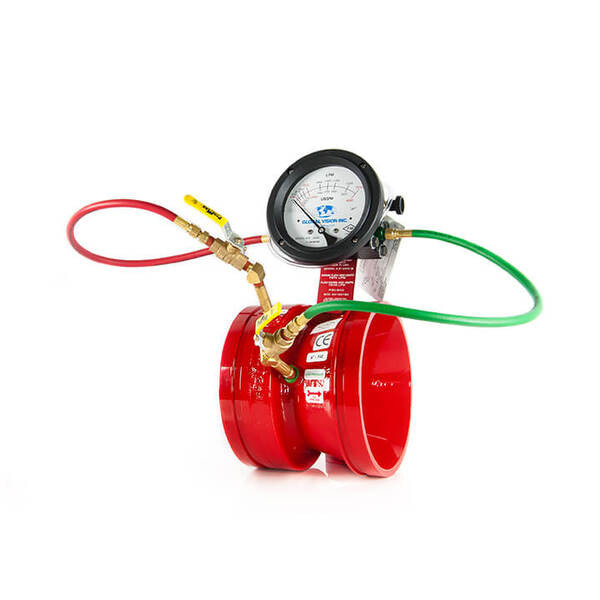
Brand: Global Vision INC (GVI)

Model: 1250-G

Flow meter permits the convenience of testing net fire pump performance frequently without the cost of assembling a large group of personnel plus providing fire hoses and nozzles for each test.

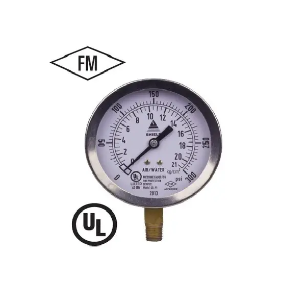
NAFFCO use flow meter of GLOBAL VISION as The new GVI digital gauge has a 4-20 ma output that can transmit flow data back to the controller, laptop or software.  There is no bounce and is by far the easiest gauge to read.  The GVI digital gauge is now FULLY FM APPROVED!!!!

Their readings were so good, we are conducting 3rd party flow testing that will prove our accuracy is closer to 0.5%.  IN ADDITION: the design is so revolutionary, we applied for a design patent which was accepted by the patent office.  This makes GVI the ONLY fire pump test meter supplier with a Patented venturi.  GVI’s new Design is FM Approved

Reviews

There are no reviews yet.

Be the first to review “FLOW METER”

Your email address will not be published. Required fields are marked *

Go to Top